- 您现在的位置:买卖IC网 > Sheet目录3840 > PIC18F6410-I/PT (Microchip Technology)IC PIC MCU FLASH 8KX16 64TQFP
PIC18F66K80 FAMILY
DS39977F-page 214
2010-2012 Microchip Technology Inc.
14.4
Timer1 16-Bit Read/Write Mode
Timer1 can be configured for 16-bit reads and writes.
When the RD16 control bit (T1CON<1>) is set, the
address for TMR1H is mapped to a buffer register for
the high byte of Timer1. A read from TMR1L loads the
contents of the high byte of Timer1 into the Timer1 High
Byte Buffer register. This provides the user with the
ability to accurately read all 16 bits of Timer1 without
having to determine whether a read of the high byte,
followed by a read of the low byte, has become invalid
due to a rollover between reads.
A write to the high byte of Timer1 must also take place
through the TMR1H Buffer register. The Timer1 high
byte is updated with the contents of TMR1H when a
write occurs to TMR1L. This allows a user to write all
16 bits at once to both the high and low bytes of Timer1.
The high byte of Timer1 is not directly readable or
writable in this mode. All reads and writes must take
place through the Timer1 High Byte Buffer register.
Writes to TMR1H do not clear the Timer1 prescaler.
The prescaler is only cleared on writes to TMR1L.
14.5
SOSC Oscillator
An on-chip crystal oscillator circuit is incorporated
between pins, SOSCI (input) and SOSCO (amplifier
output). It can be enabled one of these ways:
Setting the SOSCEN bit in either the T1CON or
T3CON register (TxCON<3>)
Setting the SOSCGO bit in the OSCCON2 register
(OSCCON2<3>)
Setting the SCSx bits to secondary clock source in
the OSCCON register (OSCCON<1:0> = 01)
The SOSCGO bit is used to warm up the SOSC so that
it is ready before any peripheral requests it.
The oscillator is a low-power circuit rated for 32 kHz
crystals. It will continue to run during all power-
managed modes. The circuit for a typical low-power
oscillator is depicted in Figure 14-2. Table 14-2
provides the capacitor selection for the SOSC
oscillator.
The user must provide a software time delay to ensure
proper start-up of the SOSC oscillator.
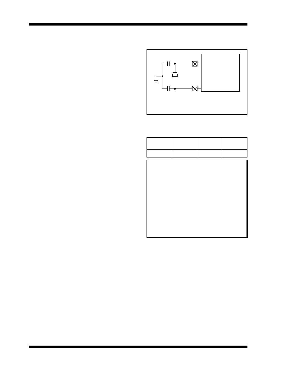
FIGURE 14-2:
EXTERNAL COMPONENTS
FOR THE SOSC
OSCILLATOR
TABLE 14-2:
CAPACITOR SELECTION FOR
THE TIMER
OSCILLATOR(2,3,4,5)
The SOSC crystal oscillator drive level is determined
based on the SOSCSELx (CONFIG1L<4:3>) Configu-
ration
bits.
The
Higher
Drive
Level
mode,
SOSCSEL<1:0> = 11, is intended to drive a wide
variety of 32.768 kHz crystals with a variety of Load
Capacitance (CL) ratings.
The Lower Drive Level mode is highly optimized for
extremely low-power consumption. It is not intended to
drive all types of 32.768 kHz crystals. In the Low Drive
Level mode, the crystal oscillator circuit may not work
correctly if excessively large discrete capacitors are
placed on the SOSCO and SOSCI pins. This mode is
designed to work only with discrete capacitances of
approximately 3 pF-10 pF on each pin.
Crystal manufacturers usually specify a CL (Load
Capacitance) rating for their crystals. This value is
related to, but not necessarily the same as, the values
that should be used for C1 and C2 in Figure 14-2.
Oscillator
Type
Freq.
C1
C2
LP
32 kHz
12 pF(1)
12 pF(1)
Note 1:
Microchip suggests these values as a starting
point in validating the oscillator circuit.
2:
Higher capacitance increases the stability of
the oscillator, but also increases the start-up
time.
3:
Since each resonator/crystal has its own
characteristics, the user should consult the
resonator/crystal manufacturer for appropriate
values of external components.
4:
Capacitor values are for design guidance only.
Values listed would be typical of a CL = 10 pF
rated crystal, when SOSCSEL<1:0> = 11.
5:
Incorrect capacitance value may result in a fre-
quency not meeting the crystal manufacturer’s
tolerance specification.
Note:
See the Notes with Table 14-2 for additional
information about capacitor selection.
C1
C2
XTAL
SOSCI
SOSCO
32.768 kHz
12 pF
PIC18F66K80
发布紧急采购,3分钟左右您将得到回复。
相关PDF资料
200346-2
CONN HOUSING RECEPT 20POS BLACK
PIC16F84A-20/P
IC MCU FLASH 1KX14 EE 18DIP
200838-2
CONN HOUSING RECEPT 34POS BLACK
PIC18LF2420-I/SO
IC MCU FLASH 8KX16 28SOIC
5172625-3
CONN RCPT HSNG 24POS BLUE PNL MT
202758-1
CONN HOUSING PLUG 6POS BLACK
TS80C31X2-VIC
IC MCU 8BIT 40/30MHZ 44-PQFP
TS80C31X2-MCC
IC MCU 8BIT 40/20MHZ 44-PQFP
相关代理商/技术参数
PIC18F6410-I/PT
制造商:Microchip Technology Inc 功能描述:IC 8BIT FLASH MCU 18F6410 TQFP64
PIC18F6410T-I/PT
功能描述:8位微控制器 -MCU 16kBF 768RM 68I/O RoHS:否 制造商:Silicon Labs 核心:8051 处理器系列:C8051F39x 数据总线宽度:8 bit 最大时钟频率:50 MHz 程序存储器大小:16 KB 数据 RAM 大小:1 KB 片上 ADC:Yes 工作电源电压:1.8 V to 3.6 V 工作温度范围:- 40 C to + 105 C 封装 / 箱体:QFN-20 安装风格:SMD/SMT
PIC18F6490-E/PT
功能描述:8位微控制器 -MCU 16kBF 768RM 68I/O RoHS:否 制造商:Silicon Labs 核心:8051 处理器系列:C8051F39x 数据总线宽度:8 bit 最大时钟频率:50 MHz 程序存储器大小:16 KB 数据 RAM 大小:1 KB 片上 ADC:Yes 工作电源电压:1.8 V to 3.6 V 工作温度范围:- 40 C to + 105 C 封装 / 箱体:QFN-20 安装风格:SMD/SMT
PIC18F6490-I/PT
功能描述:8位微控制器 -MCU 16kBF 768RM 68I/O RoHS:否 制造商:Silicon Labs 核心:8051 处理器系列:C8051F39x 数据总线宽度:8 bit 最大时钟频率:50 MHz 程序存储器大小:16 KB 数据 RAM 大小:1 KB 片上 ADC:Yes 工作电源电压:1.8 V to 3.6 V 工作温度范围:- 40 C to + 105 C 封装 / 箱体:QFN-20 安装风格:SMD/SMT
PIC18F6490-I/PT
制造商:Microchip Technology Inc 功能描述:IC 8BIT FLASH MCU 18F6490 TQFP64
PIC18F6490-I/PT
制造商:Microchip Technology Inc 功能描述:8 BIT MICROCONTROLLER CLOCK SPEED:40MHZ
PIC18F6490T-I/PT
功能描述:8位微控制器 -MCU 16kBF 768RM 68I/O RoHS:否 制造商:Silicon Labs 核心:8051 处理器系列:C8051F39x 数据总线宽度:8 bit 最大时钟频率:50 MHz 程序存储器大小:16 KB 数据 RAM 大小:1 KB 片上 ADC:Yes 工作电源电压:1.8 V to 3.6 V 工作温度范围:- 40 C to + 105 C 封装 / 箱体:QFN-20 安装风格:SMD/SMT
PIC18F6493-I/PT
功能描述:8位微控制器 -MCU 128 Segmnt LCD DRVR 12B ADC 16KB 768BRAM RoHS:否 制造商:Silicon Labs 核心:8051 处理器系列:C8051F39x 数据总线宽度:8 bit 最大时钟频率:50 MHz 程序存储器大小:16 KB 数据 RAM 大小:1 KB 片上 ADC:Yes 工作电源电压:1.8 V to 3.6 V 工作温度范围:- 40 C to + 105 C 封装 / 箱体:QFN-20 安装风格:SMD/SMT